
 |
|
| Did this site save (or help earn) you money? Say thanks with a small donation. |
The
TWI Designjet Documents library presented here as a courtesy of
ComputerCareOnline.com |
![]()
![]()
The printer's front-panel display is blank, weak or fading. Common causes include the front-panel contrast being turned down, or the front panel display itself. Follow the steps listed below to determine the actual cause of the failure and to replace the appropriate parts.
Part description | ||
|---|---|---|
Front Panel (Required) |
C6072-60175 |
C6072-60175 |
NOTE: If the printer is installed on a Multi-Roll feeder accessory, some Multi-Roll disassembly may be required to gain access to the printer. Instructions for Multi-Roll disassembly are listed at the bottom of this document for reference.
If any of the troubleshooting steps listed below solve the problem, attempt to verify printer functionality by printing several internal prints. If functionality is verified, no additional parts should be replaced.
NOTE: Ensure the printer displays some noticeable internal movement or noise before continuing with this document. If no response from printer is noticed when turned on (i.e. fan noise, vacuum noise, carriage movement, etc) use the work instruction for No Power (bpp90124).
NOTE: The menu is slightly different between Postscript (PS) ® models (1055CM, 1055CM Plus) and non-PS models (1050C, 1050C Plus).
NOTE: If removal and installation instructions are needed for reference during any repairs performed, refer to the 1000 Series Service Manual available on the Computer Care Web site for review or download.
Only remove the corresponding side cover of the Multi-Roll that requires maintenance. For example, only remove the right side cover of Multi-Roll if only the right end cover of the printer requires removal to complete the necessary service. Follow the steps listed below to gain access to the printer to complete the necessary service.
NOTE: Only ONE CE needs to be dispatched to perform service on a 1000 Series printer attached to a Multi-Roll feeder.
WARNING: Turn both the printer and the Multi-Roll feeder off and disconnect them from the power source prior to performing any maintenance.
Figure 1: Removing the screws.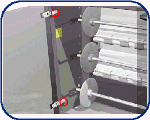
CAUTION: Be careful when removing the door not to break it.
Figure 2: Removing the two star screws.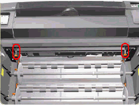
Figure 3: Removing the six T-20 screws.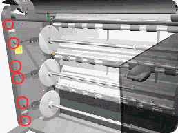
Figure 4: Removing the seven T-20 screws.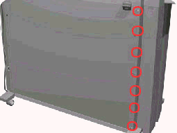
Figure 5: Removing the left side cover.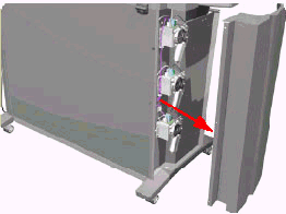
WARNING: Turn both the printer and the Multi-Roll feeder off and disconnect them from the power source prior to performing any maintenance.
Figure 6: Removing the six T-20 screws.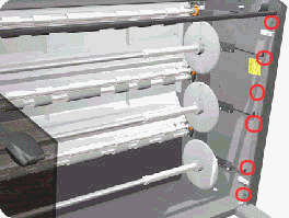
Figure 7: Removing the nine T-20 screws.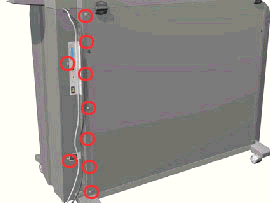
Figure 8: Opening the Rear Top cover.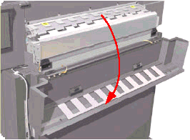
Figure 9: Releasing the cable.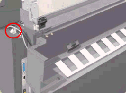
Figure 10: Removing the right side cover.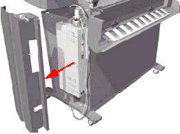
Follow the procedures listed above in reverse order.
Copyright Hewlett-Packard Co. 2002
This information is subject to change without notice and
is provided "as is" with no warranty.
Hewlett-Packard shall not be liable for any direct,
indirect, special, incidental or consequential damages
in connection with the use of this material.
Back to TWI Documents Library Index Page