
|
|
| Did this site save (or help earn) you money? Say thanks with a small donation. |
The
TWI Designjet Documents library presented here as a courtesy of
ComputerCareOnline.com |
Follow the directions below to setup an HP Designjet 5000 series printer.
NOTE: Initial setup of an HP Designjet 5000 series printer requires two CEs.
The HP Designjet 5000 printer ships in four boxes; the HP Designjet 5000PS printer - with the Take-Up Reel -ships in eight boxes.
NOTE: Read these instructions carefully and complete each stage before beginning the next.
Each box is marked to identify the contents, as shown in the following table:
Mark on box
Contents of box
Printer body
Legs assembly
Take-Up Reel (5000PS)
Take-Up Reel Tubes (5000PS)
Assorted consumables and documents
Follow these steps to unpack the printer:
CAUTION: Do not remove anti-slip material from around the wheels of the printer feet until directed to do so.
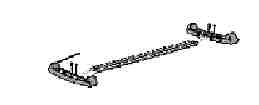
Begin by attaching the legs to the outside of the cross brace.
Attach the feet into the cross brace with screws, as shown below. Remember to leave the anti-slip material on.
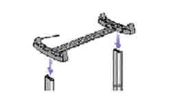
Position the feet into the leg assembly, as shown in below. Remember to leave the anti-slip material on.
Secure the feet to the legs with the six (6) screws provided.
NOTE: Some screws may have come loose during assembly. Check that all screws are fully tightened.
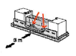
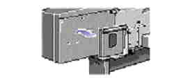
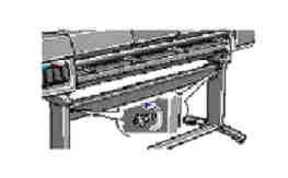
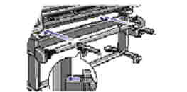
Find the handles on the rear of the printer, as shown below. There must not be any obstruction within three meters of this point.
Carefully pull aside the plastic covering and put the legs assembly on the printer. Secure with four screws.
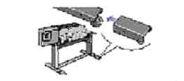
Remove the accessories from the accessory boxes, and then replace the polystyrene inside the boxes. Put the two boxes on the floor as shown below. Tilt the printer onto the boxes.
Carefully lift the printer into the upright position.
Remove the media rolls and spindle from the shipping container.
Remove the end packing and the plastic covering from the printer.
Tear off and discard the anti-slip material from the wheels.
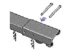
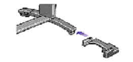
Install the two stabilizers onto the rear of the feet, as shown below. Make sure to install both stabilizers.
Install the pins into the two stabilizers and secure with the retaining clips as shown below.
Adjust the stabilizer feet so that the wheels do not touch the floor, as shown below.
Install the pocket on the rear of the printer, as shown below.
NOTE: The boxes must have the polystyrene inside to support the weight of the printer.
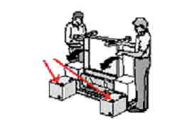
WARNING: The printer is heavy and may require two or more people to lift it into place.
NOTE: It is not necessary to lift the printer to remove the anti-slip material.
Loosen the screws shown below.
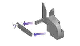
Release the clamp on the left-hand assembly by removing the screw, as shown below.
Install the left-hand assembly on the loosened screws installed in Step 1 of this section.
Pull the left-hand assembly down so that it rests securely on the screws.
Release the clamp on the right-hand assembly by removing the screw.
Install the right-hand assembly on the loosened screws installed in Step 1 of this section.
Pull the right-hand assembly down so that it rests securely on the screws.
Install the clamp and secure it with the clamp screw.
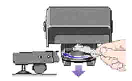
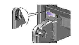
Install the front of the sensor assembly into the front of the right foot assembly as shown below.
Slide the sensor clamp firmly up against the right leg, and then secure the sensor clamp with a screw.
Tighten the screw to secure the clamp in place and connect the sensor cable.
Install the take-up reel spindle onto the printer by pushing firmly on each end of the spindle.
It is possible to use a 76 mm (3 inch) cardboard core instead of the plastic core supplied; adapters are available with the printer.
Install the adapters onto the media guides.
NOTE: Tighten all screws securing the take-up reel onto the legs
NOTE: These adapters are for use with a 76 mm (3 inch) cardboard core only.
NOTE: If the printer is an HP Designjet 1.07 m (42 inch) and a take-up reel has been ordered as an accessory, do not install the deflectors. There is a deflector integrated into the design of the bin assembly.
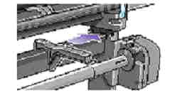
Install the left and right deflectors on top of the printer's cross brace, as shown below.
Slide deflector supports sideways until the T-piece on top of the support is inserted fully into the gap between the cross brace and the printer leg, as shown below.
The deflector bar can be found inside the core tubes, in the box. Rest the deflector bar on the two supports.
Attach end caps to the bar and supports with the two screws provided.
Turn the take-up reel on using the power switch at the rear of the take-up reel unit.
Insert the four bars into the slots in the right bin holder, and then mount the left bin holder onto the four bars.
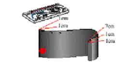
Remove the bin film from its container. Make five creases in the film at the dimensions shown in the figure below. Note the position of the red orientation dot in relation to the creases.
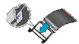
Slide the bin film into the grooves in the bin holders. Insert the end with the two creases first. Slide the film fully to the end, so that the creases are in the correct position, as shown below.
Secure the film in place at the other end with two more clips.
Install the right adapter to the rear of the right leg. The right-hand adapter is marked with the letter "R".
Install the left adapter to the rear of the left leg. The left-hand adapter is marked with the letter "L".
Insert the bin onto the adapters horizontally and insert the small pins into their slots.
Raise the bin until the large pins align with their slots and the bin drops into place.
NOTE: The bin is heavy and more than one person may be required to lift and position it.
Attach the front panel overlay to the front panel. Be sure to position the overlay cutouts correctly on the front panel locating tabs.
Install the extensions onto the media deflectors, as shown below.
Plug the power cord into the socket next to the power switch, and then into the AC power outlet.
Turn the power isolator switch at the rear of the printer to the on position.
Select the language for the front panel display using the Arrow keys, then press Enter.
When all six cartridges are installed correctly, the front panel will display the message HP ink cartridges successfully installed.
The front panel displays the printer initialization message.
When the printer has primed the ink system, the front panel displays a message to replace the setup printheads.
Open the printer window and locate the printhead carriage on the left side.
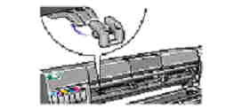
Open the printer window and pull up and release the latch on top of the carriage assembly.
Lift up the cover. This will provide access to the setup printheads.
To remove a setup printhead, lift up the blue handle and gently pull upwards until the setup printhead releases from the Carriage.
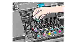
Remove the blue protective cap and the clear protective tape from the printhead's nozzles.
Push down in the direction indicated by the arrow shown below. When all the printheads are inserted correctly and accepted by the printer, the printer will beep.
If the printheads have been installed correctly, the front panel will display the message All printheads OK.
Close the cover on the carriage and shut the printer window. The front panel will display the message Open right door to access printhead cleaners.
Open the printer's right door, located just below the front panel.
Push each printhead cleaner all the way in, then press in and down until the printhead cleaner clicks into place.
After installing all printhead cleaners into the printhead service station, close the door. The front panel will display the message INK STARTUP Checking printhead CLEANERS.
Load the media, and press Enter. The front panel will display the message Calibrating printhds.
Ensure product functionality by printing internal prints/plots.
NOTE: If the printer does not beep when the last printhead is inserted, and Reseat is displayed on the front panel, try re-seating the printhead more firmly.
NOTE: When the printhead alignment is completed, the front panel will display the message Printer startup has finished.