Did this site save
(or help earn) you money?
Say thanks with a
small donation.
|
The
TWI Designjet Documents library presented here as a courtesy of
ComputerCareOnline.com
The owners of this website have no affiliation to Hewlett Packard nor do we
claim to represent HP
in any way shape or form.
Return
to TWI Documents Library Index Page
|
HP Designjet 1000 Series Printers - TWI: Noise Along the Carriage Path

In this document:

KRS document number: BPP90154
Last Updated: 27-Aug-2002
Minimum skill level: 2
Noise can usually be attributed to one of two things. The rubbing of two surfaces together due to lack of lubrication or a moving object hitting a stationary object. A few examples could be dirty or dry slider rods, damage to carriage belt, worn carriage motor, cutter, or
ink tubes. Follow the steps listed below to determine the actual cause of the failure and to replace the appropriate parts.
Parts required (part numbers are subject to change)
NOTE: If the printer is installed on a Multi-Roll feeder accessory, some Multi-Roll disassembly is required to gain access to the printer. Instructions for Multi-Roll disassembly are listed at the bottom of this document for reference.
NOTE: The fuse being sent should be used if a poor Trailing cable connection or a shorted Trailing cable blows the fuse on the Electronics module. Make sure to properly connect the Trailing cable or replace a shorted Trailing cable before installing the new fuse.
Troubleshooting steps
If any of the troubleshooting steps listed below solve the problem, attempt to verify printer functionality by printing several internal prints. If functionality is verified, no additional parts should be replaced.
- Turn the printer off.
- Open the
Printhead cleaner door, located on the right side of the printer.
- Pull the Printhead cleaner tray all the way forward.
- Lift the printer's Top cover.
- Pull the Carriage assembly out from its home position to the left.
- Slide the Carriage left and right across the Carriage path.
- If the noise occurs while sliding the Carriage assembly, continue with Step 8. If no noise is heard, continue with Step 11.
- Check that the Cutter is not engaged (down position). If so, hold the carriage with your right hand, and with your left hand, press
the cutter lever towards the right, to raise the cutter.
- Using a lint-free cloth, dampened with warm water, wipe the Carriage rails along the entire length of the Carriage path.
- Completely dry all water from the rails.
- Move the Carriage to the middle of print area.
- Use Oil Applicator or put two small drops of HP Synthetic Oil on the Carriage rails on each side of the Carriage and using a lint-free cloth, wipe the lubricant along each side of the Carriage rails.
- Manually move the Carriage from side-to-side, across the entire print path several times.
- If Carriage continues to make noise, repeat steps 11 through 13 at least two times before continuing with the remaining steps.
- If noise continues, examine the Carriage belt for wear and replace if needed (replace the Tensioner assembly if belt is replaced), refer to page 8-44 8-37 of the Service Manual.
NOTE: If removal and installation instructions are needed for reference during any repairs performed, refer to the 1000 Series Service Manual available on the Partner Care Web site for review or download.
- Following replacement, attempt to verify functionality.
- If the problem persists or no problems were found, replace the Carriage assembly (refer to page 8-44 of the Service Manual).
- During the Carriage assembly replacement, check and clean the Encoder strip, and replace if damaged (refer to page 8-34 of the Service Manual).
- Lower the printer's Top cover and close the Printhead cleaner door (door on right side).
- Turn the printer on and allow initialization to complete.
- If no noise is noticed during printer initialization, perform Service Calibrations 2, 3, 4, 6, 8, and the Carriage Height Calibration (instructions listed below).
- Following successful calibrations, turn the printer off, then on and attempt to verify functionality.
- If the noise occurs during initialization, or the noise continues following part replacement, continue with the Scan Axis test.
Scan Axis Test
WARNING: All cover sensors are disabled when in the Service Test sub-menu. If the Carriage is moving it will not stop if the window is opened, so be careful not to put your hands inside.
- Turn the printer off using the power switch on the front of the printer.
- Hold down the Color key and turn the printer on.
- Once inside the Service Tests menu, scroll to 5. Scan Axis, and press Enter.
- Allow the printer to complete the test.
- When finished, SCAN AXIS FORWARD values will be displayed on the front-panel, note all five values and press Enter.
- The SCAN AXIS BACKWARDS values will now be displayed, again note the five values.
- Use the table below to determine if the values are within the printer limits:
|
|
|
|
|
| |
Scan-Axis Forward |
Scan-Axis Backwards |
Normal |
Maximum |
Normal |
Maximum |
Average PWM |
165 |
185 |
-165 |
-185 |
Maximum PWM |
220 |
240 |
220 |
240 |
Stabilize Dist. |
1800 |
2400 |
1800 |
2400 |
Average Speed offset |
2.4 |
10 |
2.4 |
10 |
STD Speed offset |
4.4 |
10 |
4.4 |
10 |
- If the values obtained are less than the Maximum values listed in the table the test has passed. Turn the printer off then on, and attempt to verify functionality.
- If the values are greater than the Maximum allowed values, oil the Slider rods and repeat the Scan Axis test.
- If the test passes, turn the printer off then on, and attempt to verify functionality.
- If the values are still out of range, replace the Scan-Axis motor (refer to page 8-33 of the Service Manual).
- Following replacement, perform the Scan-Axis test again.
- Verify printer functionality.
Performing Service Calibrations
NOTE: Printer menu mode must be set to Full to access the Service Tests submenu. To verify, at the Ready prompt, scroll to the Printer Setup icon, and press Enter. Use the Arrow keys to scroll to the Utilities menu and press Enter. Using the Arrow keys scroll to Menu Mode =. Select Full (if needed) and press the Back key to return to the main menu.
- With the printer turned on, scroll to the Printer Setup Menu (Icon of printer in lower right side of the front panel display) and press Enter.
- Using the Arrow keys scroll to Utilities, and press Enter.
- Press the Up Arrow and Enter keys simultaneously.
- Scroll to Service Calibrations and press Enter.
- Scroll to the needed Service Calibration and press Enter.
- Follow instructions displayed on the front panel to complete the selected calibration.
- When calibration is finished, stay in service mode to perform any additional calibrations (if required).
- When all required calibrations are complete, return to the main Status display using the Back key.
- Turn the printer off.
- Turn the printer on, and attempt to verify functionality.
Multi-Roll feeder disassembly
Only remove the corresponding side cover of the Multi-Roll that requires maintenance. For example, only remove the right side cover of Multi-Roll if only the right end cover of the printer requires removal to complete the necessary service. Follow the steps listed below to gain access to the printer to complete the necessary service.
NOTE: Only one CE needs to be dispatched to perform service on a 1000 series printer attached to a Multi-Roll feeder.
Removing the Multi-Roll feeder left side cover
WARNING: Turn both the printer and the Multi-Roll feeder off and disconnect them from the power source prior to performing any maintenance.
- Open the left door of the Multi-Roll feeder.
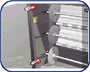
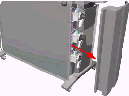
- Loosen the two screws that secure the left door to the Multi-Roll feeder (see Figure 1).
- Remove the left door.
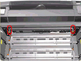
- Remove the two star screws (orange) that secure the Front top-cover to the Multi-Roll feeder (see Figure 2).
- Remove the Multi-Roll feeder top cover.
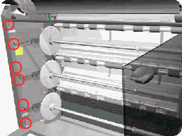
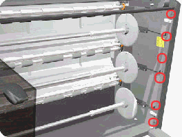
- Remove six T-20 screws that secure the left Side cover to the Multi-Roll feeder from the front (see Figure 3).
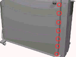
- Remove the seven T-20 screws that secure the left side cover to the Multi-Roll feeder from the rear (see Figure 4).
- Remove the left side cover (see Figure 5).
Removing the Multi-Roll feeder right side cover
WARNING: Turn both the printer and the Multi-Roll feeder off and disconnect them from the power source prior to performing any maintenance.
- Remove the right door and front top cover from the Multi-Roll feeder (follow steps 1 through 5 of the previous section and remove the right door instead of the left).
- Remove six T-20 screws that secure the right side cover to the Multi-Roll feeder from the front (see Figure 6).
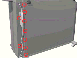
- Remove nine T-20 screws that secure the right side cover to the Multi-Roll feeder from the rear (see Figure 7).
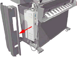
- Open the rear top cover (see Figure 8).
Figure 8: Rear top cover
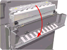
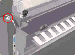
- Release the cable that is attached to the top of the right side cover (see Figure 9).
- Remove the right side cover (see Figure 10).
Installation of covers
Follow the procedures listed above in reverse order.
Copyright Hewlett-Packard Co. 2001
This information is subject to change without notice and
is provided "as is" with no warranty.
Hewlett-Packard shall not be liable for any direct,
indirect, special, incidental or consequential damages
in connection with the use of this material.


![]()
![]()
