Did this site save
(or help earn) you money?
Say thanks with a
small donation.
|
The
TWI Designjet Documents library presented here as a courtesy of
ComputerCareOnline.com
The owners of this website have no affiliation to Hewlett Packard nor do we
claim to represent HP
in any way shape or form.
Return
to TWI Documents Library Index Page
|

In this document:

Document number: BPP90070
Last updated: 17-Jan-2003
Minimum skill level: 2
The
printhead Carriage
cannot move, or has difficulty moving freely. Common causes are obstructions in the
Carriage path, excess friction along the Carriage path, and worn or damaged Y-axis parts. Use the steps listed in this document to determine the cause of the failure and replace the appropriate parts.
NOTE: If the printer is installed on a Multi-Roll feeder accessory, some Multi-Roll disassembly is required to gain access to the printer. Instructions for Multi-Roll disassembly are listed at the bottom of this document for reference.
Parts required (part numbers are subject to change)
Troubleshooting steps
If any of the troubleshooting steps listed below solve the problem, attempt to verify printer functionality by printing several internal prints. If functionality is verified, no additional parts should be replaced.
- Turn the printer off, using the power switch on the back of the printer.
- Unload media and check for obstructions in the Carriage path.
- Check for jammed media. If there is a jam, follow the steps directly below. If there are no jams, continue with Step 4.
- Slide the
cartridge Carriage out of the way toward either side of the enclosed ends of the printer (if needed).
- Lift the ARSS release lever.
- Remove any of the jammed media that is easily lifted up and out from the top of the printer.
- Pull the rest of the roll or sheet down and out of the entry slot where the media is loaded.
- Check around the ends, front, and rear edges of the
platen roller to verify that all of the torn media is removed. A manila folder can be used to remove jammed media from the media path (take care not to damage the
media sensor on the right side of the printer).
- Lower the printer window and the ARSS lever and turn the printer on. After initialization, press the Form Feed And Cut key to eject any pieces of media that might still be in the media path.
- Reload the media as normal. If using roll, trim the edge so the media is straight before loading. Also, be sure not to load the media upside down.
- If loading is successful, repeat loading procedure with both roll and sheet media (preferably larger than 8 1/2 x 11 inches) two times each, to prove functionality. If everything works well, no parts need to be replaced.
- If loading is unsuccessful or problems persist, continue with Step 4.
- Clean the Carriage slider rods and apply oil along the complete axis of the slider rods.
- Gently clean the
encoder strip with a lint-free cloth dampened with water. Replace the
encoder strip if it is visibly damaged
(refer to pages 8-34 of the Service Manual).
- Trip the window sensor using a pen cap or small piece of media.
- Turn the printer on.
- Watch the Carriage movement during initialization. Make sure the cables attached to the
Carriage assembly do not obstruct the Carriage movement anywhere along the entire Carriage path. Fix as necessary and attempt to verify functionality.
- If the error states "Switch Power Off, Check Printhead Path (1)" and the Carriage stops all the way to the left, above the cartridges, perform the steps directly below. If this is not the case continue with the next section (Scan Axis test).
- Remove the
left
cover.
- Remove the cutter actuator arm from the tensioner assembly.
- Re-install the tubes and cartridges.
- Turn the printer on and run a test print.
- If the error appears, continue with the next section (Scan Axis test).
- If the error does not appear, turn the printer off, then on and run another test print.
- If problems persist, continue with the next section (Scan Axis test).
Scan Axis test
- Turn the printer off using the Power switch on the front of the printer.
- Hold down the Color key and turn the printer on.
NOTE: Wait until the message, "Initializing" appears, and then release the Color key.
- Once inside the Service Tests menu, scroll to 5 Scan Axis, and press Enter.
- Allow the printer to complete the test.
- When finished, SCAN AXIS BACKWARDS values will display on the front panel. Note all five values and press Enter.
- The SCAN AXIS FORWARD values will now appear. Again, note the five values.
- Use the table below to determine if the values are within the printer limits:
|
|
|
|
|
| |
Scan-Axis Forward |
Scan-Axis Backwards |
Normal |
Maximum |
Normal |
Maximum |
Avg. PWM |
165 |
185 |
-165 |
-185 |
Max. PWM |
220 |
240 |
220 |
240 |
Stabilize Dist. |
1800 |
2400 |
1800 |
2400 |
Avg. Speed offset |
2.4 |
10 |
2.4 |
10 |
STD Speed offset |
4.4 |
10 |
4.4 |
10 |
- If the values obtained are less than the maximum listed in the table, the test has passed. Turn the printer off then on, and again try to verify functionality.
- If the values are greater than the maximum allowed, oil the slider rods and repeat the Scan Axis test.
- If the test passes, turn the printer off then on, and try to verify functionality.
- If the values are still out of range, replace the
Scan-Axis motor
(refer to pages 8-33 of the Service Manual).
- Following motor replacement, perform the Scan-Axis test again.
- If the values are within the limits, turn the printer off then on, and try to verify functionality.
- If the values continue to stay out of range following motor replacement, replace the
trailing cable and
carriage belt
(refer to pages 8-44 and 8-39 of the Service Manual).
- After replacement, perform the following calibrations:
- Line Sensor
- Service Station
- Roller Mark Position
- Color to Color
- Pen Alignment
- Following successful calibrations, attempt to verify functionality.
- If problems persist, continue with the remaining steps.
Multi-Roll feeder disassembly
Only remove the corresponding side cover of the Multi-Roll that requires maintenance. For example, only remove the right-side cover of Multi-Roll if only the right-end cover of the printer requires removal to complete the necessary service. Follow the steps listed below to gain access to the printer to complete the necessary service.
NOTE: Only one CE needs to be dispatched to perform service on an HP Designjet 1000 series printer attached to a Multi-Roll feeder.
Removing the Multi-Roll feeder left-side cover
WARNING: Turn both the printer and the Multi-Roll feeder off and disconnect them from the power source prior to performing any maintenance.
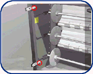
- Open the left door of the Multi-Roll feeder.
- Loosen the two (2) screws that secure the left door to the Multi-Roll feeder.
- Remove the left door.
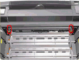
- Remove the two (2) star screws (Orange) that secure the front-top cover to the Multi-Roll feeder.
- Remove the Multi-Roll feeder top cover.
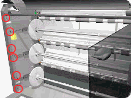
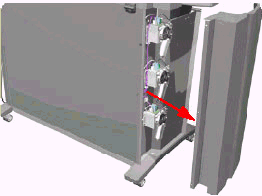
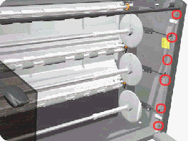
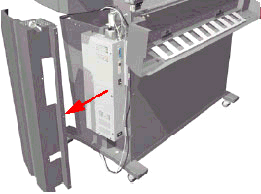
- Remove six (6) T-20 screws that secure the left-side cover to the Multi-Roll feeder from the front.
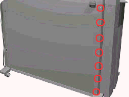
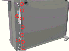
- Remove the seven (7) T-20 screws that secure the left-side cover to the Multi-Roll feeder from the rear.
- Remove the left-side cover.
Removing the Multi-Roll feeder right-side cover
WARNING: Turn both the printer and the Multi-Roll feeder off and disconnect them from the power source prior to performing any maintenance.
- Remove the right door and front-top cover from the Multi-Roll feeder (follow Steps 1 through 5 of the previous section and remove the right door instead of the left).
- Remove six (6) T-20 screws that secure the right-side cover to the Multi-Roll feeder from the front.
- Remove nine (9) T-20 screws that secure the right-side cover to the Multi-Roll feeder from the rear.
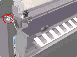
- Open the rear-top cover.
Figure 8: Rear-top cover
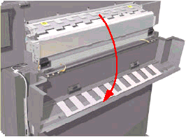
- Release the cable that is attached to the top of the right-side cover.
- Remove the right-side cover.
Installation of covers
Follow the procedures listed above in reverse order.
Copyright Hewlett-Packard Co. 2001
This information is subject to change without notice and
is provided "as is" with no warranty.
Hewlett-Packard shall not be liable for any direct,
indirect, special, incidental or consequential damages
in connection with the use of this material.


![]()
![]()
