Did this site save
(or help earn) you money?
Say thanks with a
small donation.
|
The
TWI Designjet Documents library presented here as a courtesy of
ComputerCareOnline.com
The owners of this website have no affiliation to Hewlett Packard nor do we
claim to represent HP
in any way shape or form.
Return
to TWI Documents Library Index Page
|

In this document:

Document number: BPP90052
Last updated: 13-Jan-2003
Minimum skill level: 2
The
Line sensor on the Carriage cannot find the Mark encoder located on the left side of the Drive roller. A dirty mark encoder or malfunctioning line sensor on the
Carriage are the two biggest causes of this system error. In some cases, the Mark encoder may be missing from the Drive roller. Follow the instructions listed below to accurately troubleshoot the issue, replace the appropriate parts, and perform the necessary calibrations.
Parts required (part numbers are subject to change)
Troubleshooting the Mark Encoder
If parts are replaced or fixed in any of the steps listed below, attempt to verify printer functionality by turning the printer on and printing internal test prints. If functionality is verified, no additional parts should be replaced.
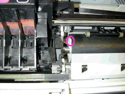
- Verify the Mark encoder is still attached to the Drive roller (refer to Figure 1).
- If the Mark encoder is visible, clean if needed per Step 14. If no cleaning is needed, continue with troubleshooting the Y-axis positioning.
- If the Mark encoder cannot be seen, make sure the printer is turned off from the power switch on the back of the printer.
- Hold the Up Arrow key and the Enter key down and turn the printer on.
NOTE: Continue to press both the Up Arrow and Enter keys until letters begin to scroll on the lower right corner of the front-panel display.
- Once the message Status/Ready is displayed on the front panel, press the Enter key.
- Use the Arrow keys to scroll to the Utilities and press Enter.
- Scroll to the Service Tests and press Enter.
NOTE: Full menu mode must be set to access the Service Tests submenu. In the Utilities menu, scroll to Menu Mode and select Full.
- Scroll to the Diagnostics and press Enter.
- Scroll to D15 Clean Roller and press Enter.
- The Unload Media message will be displayed remove media (if loaded).
- The Move Roller message is now displayed. Use the Up Arrow key to begin rotating the drive roller.
- As the drive roller rotates, look for the Mark encoder.
- If the Mark encoder is damaged or missing, replace the Mark encoder and continue with Step 15.
- If the Mark encoder is dirty, clean with a Q-tip or lint-free cloth dampened with water, and continue with Step 15.
- Turn the printer off, then on, and allow printer to initialize.
- If no error is reported, verify printer functionality by printing several internal prints.
- If the error reappears, continue with troubleshooting the Y-axis positioning.
Troubleshoot Y-axis positioning
- Turn printer off using the power switch on the back of the printer.
- Clean and
lubricate the Carriage rails. Remove all foreign objects from the
Carriage rails and make sure the end stops are free of any contaminants that could be causing the Carriage not to reach home position (both end covers may need to be removed to clearly see entire Carriage path).
WARNING: Do not perform the following step with a customer, as the
Encoder strip is very sharp and can cause injury. Only On-site technical support engineers can clean the
Encoder
strip.
- Gently clean the
Encoder strip with a lint free cloth dampened with water. If needed,
replace the Encoder
strip. Attempt to verify functionality before continuing with remaining steps; no further parts need to be replaced if functionality is proven.
- Visually inspect the
Y-axis belt for damage, or wear.
Replace the Y-axis belt if necessary (refer to pgs. 8-39 of the service manual). Attempt to verify functionality before continuing with remaining steps, no further parts need to be replaced if functionality is proven.
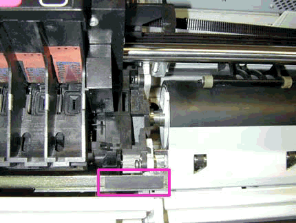
- Make sure the rubber tabs (pictured in Figure 2) on both ends of the Overdrive are not obstructing the Carriage or
Cutter movement. The Corners of the rubber tabs may pull up, or the entire tab may have moved causing an obstruction in the
Carriage or
Cutter path. Reposition tab(s) as needed.
- Turn printer on, and check for proper Y-axis positioning.
- If the Line sensor (Carriage) positioning still appears to be incorrect, attempt further troubleshooting on the Y-axis.
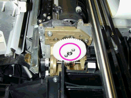
- If Y-axis positioning appears correct, tighten the X-axis helical gear screws (pictured in Figure 3) and continue with Step 9.
- Turn printer on, if the error reappears, continue with troubleshooting the line sensor (listed below).
- If no error appears, verify printer functionality by printing several internal prints. If functionality is proven, no additional parts need to be replaced.
Troubleshooting the Line Sensor
- Verify the Line sensor is not damaged or missing.
- If the Line sensor is damaged or missing, continue with replacing the Carriage and
Trailing cable as instructed below.
- If the Line sensor appears correct, replace the Lens cover and perform the Line sensor calibration C03 (instructions listed below).
- If the calibration passes, verify printer functionality by printing several internal prints. No additional parts need to be replaced.
- If the calibration fails, continue with replacing the Carriage and
Trailing
cable.
- Turn the printer off.
- Replace the Carriage and
Trailing cable (refer to pgs. 8-36, 8-42 of the service manual).
- Perform calibrations C02, C03, and C08 (instructions listed below). All other calibrations will be completed when printer is turned on in Normal mode (during printer initialization).
NOTE: Following each calibration, turn the printer off to store the new calibration values in the EEROM. Turn the printer on (entering Service mode) to perform the next required calibration. Repeat this cycle until all necessary calibrations have been performed.
Performing Service Calibrations
Following each calibration, turn the printer off to store the new calibration values in the EEROM. Turn the printer on (entering Service mode) and perform the next required calibration. Repeat this cycle until all necessary calibrations have been performed.
- Make sure the printer is turned off from the power switch on the back of the printer.
- Hold the Up Arrow key and the Enter key down while turning the printer on.
NOTE: Continue to press both the Up Arrow key and the Enter keys until letters begin to scroll on the lower right corner of the front-panel display.
- Once the message Status/Ready is displayed on the front panel, press Enter.
- Use the Arrow keys to scroll to the Utilities menu display and press Enter.
- Scroll to Service Tests and press Enter.
- Scroll to Service Calibrations and press Enter.
- Use the Arrow keys to scroll through the specific calibrations and press Enter when the required calibration is displayed.
NOTE: For the best results when performing the Accuracy calibration, use a Polyester Matte film. If Polyester Matte film is not available, use HP High Gloss or Heavy Coated media.
Copyright Hewlett-Packard Co. 2001
This information is subject to change without notice and
is provided "as is" with no warranty.
Hewlett-Packard shall not be liable for any direct,
indirect, special, incidental or consequential damages
in connection with the use of this material.


![]()
![]()


